Assembly & Procedure: Agricultural Robot
Scroll ↓
-
Sept - Nov 2025
-
Myself & liaising with the client
*** with support from our in-house fitter when needed
-
Assemble 2 out of the 3 robots, and update the assembly procedure documentation
-
Two assembled robots
Documented procedure
Improved assembly efficiency and effectiveness
-
BDGT Precision Engineering
The Bunk Scanner is a robot used in the Agricultural industry, which roams up and down dirt roads. Experiencing ample vibrations and a harsh environment, this project has undergone multiple field breakdowns and drawing revisions. To support our client, I completed one assembly to understand the design. Then I updated and improved the procedure, before validating it by assembling a second one.
Key Assembly Points
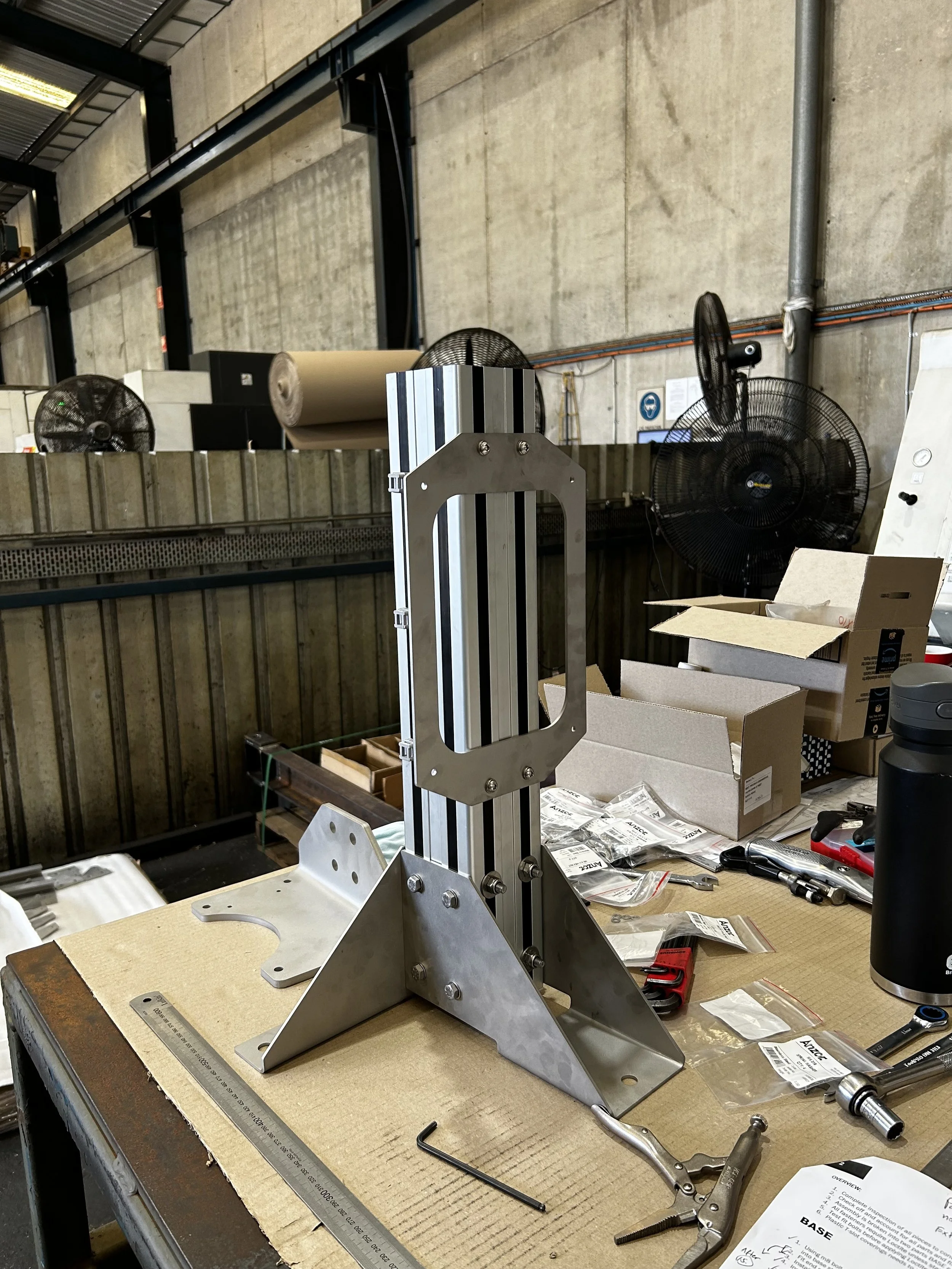
Base
Structural sub-assembly
Parallel bottom plates to ensure a 90-degree vertical strut
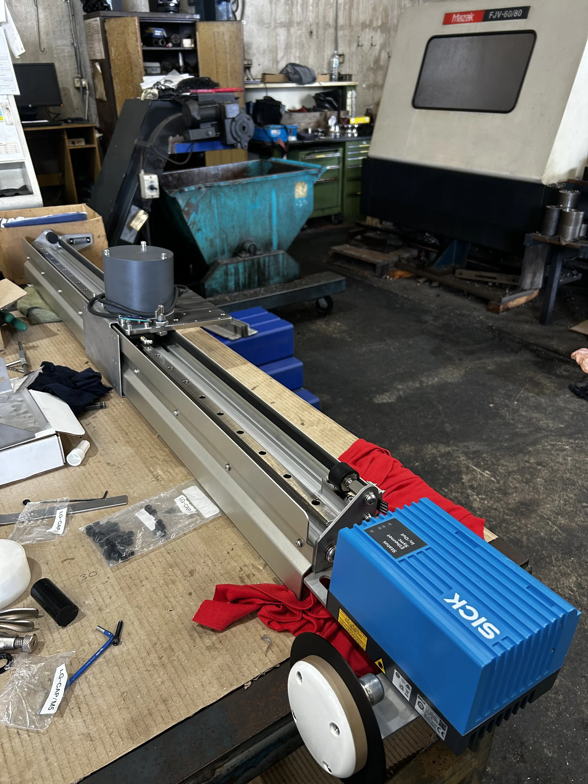
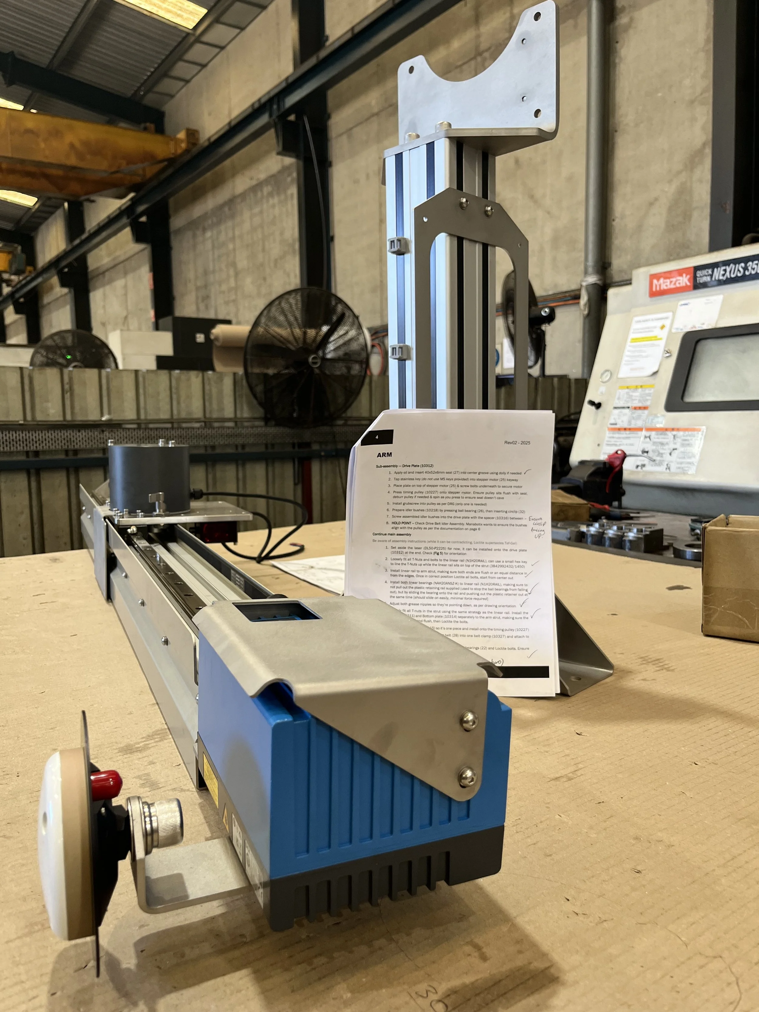
Arm
Smooth movement of the drive on the linear rail
Correct alignment of mechanical components
Optimized component attachment order
Procedure/Documentation
After doing the first assembly, I understood the order in which specific parts needed to be attached/assembled to minimise downtime.
I’ve summarized key points and thoughts from my assembly procedure for you below.
Loctite vs Tef-Gel (anti-sieze), when to use either one
Ordering the fitting of components to optimise efficiency
Specifying orientations that are difficult to extract from the drawing
Recommending the use of dollies and special equipment
Outlining the client’s design intent, to support the fitter in being more effective
Outcome
I was able to reduce this project’s assembly time by 25%, from 20hrs to 15hrs. Increasing profits on the job and improving efficiency for future orders.
Completing this project independently helped me appreciate and understand the process involved in fitting structural and mechanical components. It also revealed the design intent behind various parts, and comprises made in designing for manufacturing.
Writing the procedure allowed me to explore alternative methods of assembly to find the most efficient one, and revealed possible design revisions that I later recommended to the customer, to further improve production efficiency and effectiveness.